WorldSkills Jamaica, in collaboration with Global Partner Studica Robotics, recently presented a mobile robotics workshop.
The FIRST® Robotics Competition (FRC) has released the details of this year's game, CRESCENDO, presented by Haas.
In this article, we will provide all the information you need to build a mecanum drivetrain. We will detail the components needed and provide step-by-step building instructions. To make it simple, we've created this build guide using components that can all be found in the FTC Drive Base Kit from Studica Robotics. Studica Robotics offers durable components that are strong and safe, making them well-suited for students and robotics teams. You can also view our detailed Drivebase Build Guide.
The answer to this is dependent upon what you need your robot to do or what robotics competition you will be competing in. If you are looking for a robot that can maneuver easily in limited spaces, a mecanum chassis may be the best solution for you. This a four-wheel drivetrain where each of the wheels is powered individually by a motor. Each wheel in this drivebase has rollers angled at 45°, allowing for holonomic movements such as strafing or rotating in place. This is particularly useful for the current FIRST ® Tech Challenge 2023-2024 CENTERSTAGESM presented by RTX competition.
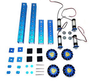
To complete this build, everything you need can be found in the FTC Drive Base Kit from Studica Robotics. Structure components include U-channel, end piece plates, and U-channel bumpers. Motion components include a gearmotor, orbital mount plates, tooth bevel gears, D-shaft, clamping shaft hub, D-shape collar clamp, and mecanum wheels. Screws, nuts, and spacers are also included. You can view all the materials needed here.
This is a summary of the steps that need to be taken to build your Mecanum chassis. If you are looking for more detailed instructions with visual cues, click here. We've divided this build into three steps. First, we will walk you through the assembly of the frame, then prepare the gear motors and mecanum wheels. Once everything is prepared will assemble the drive base. You will find additional coding information below.
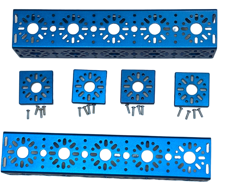
To start this drivetrain project you will assemble the structure components to build the basic frame. You will attach the end piece plates to the 240mm U-Channels with the socket head cap screws. Then you will attach the 240mm U-channel to the 432mm U-channels with the socket head cap screws. The 432mm U-channels have 9 hold patterns. The 240 mm U-channels should be placed at hole pattern #5 and #9 to connect the 432mm U-channel pieces. View detailed instructions.
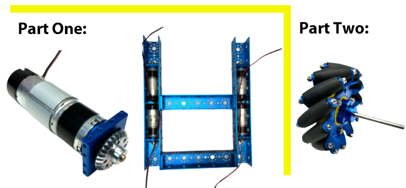
Part One: A. Screw the motors onto the orbital mount plate with the socket head cap screws.
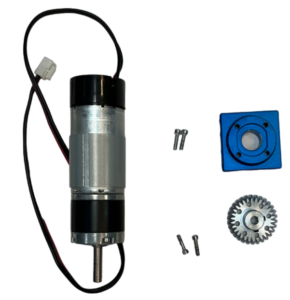
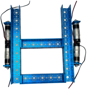
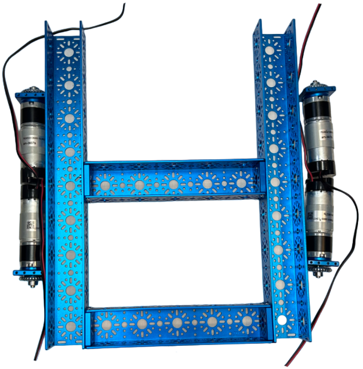
B. Then attach one of the tooth bevel gears to the motor shaft and tighten. Then secure the orbital mount plate to the 432 mm U-channels with four socket head cap screws on each plate. The motors will recess in the 432mm U-channels.
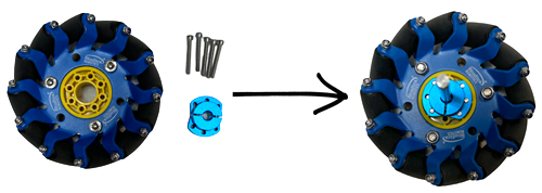
Part Two: Prepare the four mecanum wheels by screwing the clamp shaft hub to them using six socket head caps screws on each wheel.
✔ This is how your items will look after these steps are completed.
Now, let's put your drivetrain together! On the hole pattern that is adjacent to the bevel gear attached to the motor shaft, place the flange bearings onto the 432mm U-channel. Insert the D-shaft into the clamping shaft hub so that it is aligned with the shaft. Insert the shaft through the flange bearings and tooth bevel gear on the 432mm U-channel. Before you do anything else, make sure that the driving gear on the motor shaft and the driving gear on the wheel shaft mesh with each other. ✔ Check the teeth of the gears to see if they fit easily into each groove. This will allow them to turn effectively.
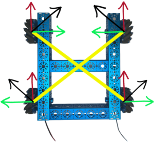
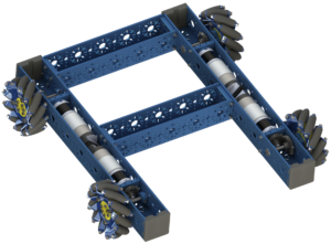
✔ Next, make sure your wheels are oriented as they are in the image to the right. Illustrated with yellow, you can see when you draw a line parallel to the angle of the rollers it creates an "X" shape. The force vectors are represented by the black arrows. You can add up the force vectors generated by the angle of the rollers to move in any direction. The red and green arrows represent the X and Y axes of movement that are made possible due to how the rollers are orientated in the build. Then simply place the D-shape collar clamp at the ends of the D-shaft and secure it by tightening the clamp with a screw.
Here is the Onbot Java code that you will use for your drivetrain for use in FTC. Three variables are being used, (X, Y, and RX), that represent the three axes of movement of this mecanum drive base. The left stick will control the movement on the X and Y axis for forward, backward, and strafing from left to right motion. RX is the rotational movement variable. The denominator variable is the absolute value of the largest motor power or one. We want to keep the power ratio between -1 and 1. (View PDF for clearer coding instructions.) In conclusion, we hope you enjoyed this mecanum drivetrain building guide. Again, if you'd like to work on this project, all the materials needed are included in the FTC Drive Base Kit from Studica Robotics. You can view our detailed building guide or a PDF of the instructions. Enjoy!
In this article, we will walk you through the steps of building a pushbot using the FTC Starter Kit from Studica Robotics.
CAN is the abbreviation used for a Controller Area Network. Let's explore how CAN bus is used in mobile robotics.
The WorldSkills Museum is the first of its kind. This new museum is completely devoted to vocational skills.
The mission of Colorado FIRST is to deliver top-notch FIRST Robotics programs to students across Colorado and develop the leaders of tomorrow.
Motion components play a large role in robotics, but with so many choices it can often be confusing. In this article, we will explore a variety of robot wheels. This helpful guide focuses on mobile robotics and creating robots for robotics competitions. It is designed to help you select the best wheels for your robot. Let's dig deeper into the composition of the different types of wheels and explain the use cases for each.
What wheels should you use for your robot? Choosing the correct wheels for your robot is a critical decision for your robot that will directly impact its mobility, performance, and stability. Below we will explore common types of wheels for mobile robotics competitions including mecanum wheels, omni wheels, standard wheels, all-terrain robot wheels, and compliant wheels.
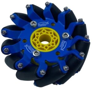
Mecanum wheels provide traction and stability for omnidirectional movement. Movements you can achieve include standard forward and backward motion, rotating around a fixed axis, and strafing from side to side or at an angle. An example is the 100mm slim mecanum wheel from Studica Robotics. As you can see, the wheel is comprised of 12 rollers that are orientated 45° to the axis of rotation of the wheel. These wheels are powered individually. The angle of the rollers allows your robot to perform a wide range of movements. Steel ball bearings make the roll more fluent. A benefit to this 100mm slim wheel is that it allows for the design of a wider base robot.
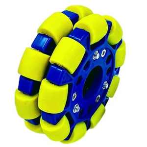
Similar to the Mecanum wheel, Omni wheels are useful for creating omnidirectional movement. These wheels have rollers around their circumference. However, in this case, the wheels are perpendicular to the wheel plane. These wheels will move forward and backward and strafe from side to side. They provide flexibility when designing your drive base. For example, you can build a 4-wheel drive, 3-wheel drive, or just have two wheels powered on a 4-wheel drive. Omni wheels are excellent for use in applications that require high maneuverability. Shown here is a
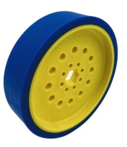
 100mm (4 inches) double plastic omni wheel that is ideal for fast turning, and offers easy direction control and tracking.
How do you know if you need Omni or Mecanum wheels? These questions can help you decide.
Standard wheels, also referred to as drive wheels, are designed to perform on smooth, flat surfaces. They are commonly used for indoor mobile robots and are generally made out of materials such as soft plastic or rubber. As an example, here we have a 100mm drive wheel (4") 50A, 25mm wide, 1/2" inner hex in blue. The inner material is molded plastic and the exterior material is TPU polyurethane. At Studica Robotics, you can find standard drive wheels available in a variety of sizes and durometers. Options include 100mm 50A - 12.5mm wide, 100mm 50A - 25mm wide, 50mm 35A -25mm wide, 50mm 40A-25mm, 50mm 50A - 25mm wide, 50mm - 60A -25 mm wide, and 75mm 60A -12.5mm drive wheels.
Compliant wheels also known as flex wheels are not intended for moving your robot, they are designed for moving objects. You can also modify Studica Robotics flex wheels for better intake. This comes in handy when there are multiple-sized objects to intake for your robot. To do this, you can simply remove the top edges of the wheel by cutting them allowing the wheel to be star-shaped. Once the wheel has been cut, it can flex even more. Compliant wheels are available at Studica Robotics in 35A, 40A, 50A, and 60A durometers.
Treaded wheels also referred to as all-terrain robot wheels are paired with shock absorbers and are ideal for traversing rough, uneven terrains. They should be used for applications that require high traction. The example below is the All-Terrain Wheel Pack from Studica Robotics. It includes two left and two right rubber wheels that have foam cores and therefore do not require air. They've been tested up to 40 kg (88 lbs) using all four wheels. They offer excellent traction on smooth, solid surfaces and are particularly well-suited for navigating uneven terrains, including areas with mulch, sand, dirt, or gravel.
An innovative building platform that prioritizes quality and safety, Studica Robotics offers a wide variety of robot parts, robotics kits, and cutting-edge electronics. This article will focus on the variety of linear servo actuators available from Studica Robotics. These actuators are unique because they allow for the adjustment of the extending shaft to a specific length. Actuators are devices that cause an action to happen by converting electric signals into some form of motion. While the multi-mode smart servo creates a precise movement in an angular direction, linear servo RC actuators move a rod back and forth on a linear path. You could also use a regular motor or a servo motor with a rack and pinion linear slide set to achieve this, however, the linear servo RC actuators simplify the process. There are several options available, this article will help you determine the linear servo actuator that best fits your needs.
There are several linear servo RC actuators available from Studica Robotics. We will share use cases for each.
Studica Robotics is a comprehensive robotics platform with everything you need to build, learn, and compete. Our durable, affordable structure components are easy to assemble and connect to our wide range of motion components. Our electronics, from controllers to sensors, empower your robot with cutting-edge capabilities. Our VMX controller is versatile and programmable in multiple languages, making it ideal for complex projects and autonomous robots. We are committed to innovation and excellence, as evidenced by our partnership with WorldSkills and our exclusive supply of robotics components for the Autonomous Mobile Robotics Competition. Discover your true building potential with Studica Robotics.
If you are building a robot for a robotics competition, class project, or your own personal joy - prototyping is a crucial step in engineering design. After you have decided what you want your robot to do and adjusted for any specific parameters, you can start to brainstorm what your design will be. Once you have your design sketched out or a CAD model created, it is time to test and refine. In simple terms, robot prototyping is the process of taking your ideas, creating a preliminary mock-up of your robot design, testing, collecting data, adjusting, and more testing until we get to the desired level of performance. Be sure to test your mechanisms, designs, and even your robot performing the tasks that are required of it. The purpose of this process is to ensure your robot design is corrected for any flaws and can complete the task as it is designed. Your tests should reflect the purpose of the type of robot you are creating. Autonomous mobile robots such as field robots should be challenged with tasks related to their purpose. For example, this photo shows a prototype of a lift that we are working on using parts from the Studica Robotics FTC Starter Kit.
The main goal of prototyping for robotics is simple - test your design and gather data, review the results, and find ways to fix any issues and improve your robot's performance. Think of it as a journey - as you identify each change and adjust your robot prototype, you will need to re-test it. Have patience, this is not a one-and-done. As you progress through this process, you can gradually increase the fidelity of your prototype. What does it mean to increase the fidelity of your prototype? This simply means that you continually enhance and add details to your prototype to the point where it bears a strong likeness to what your final robot will look and behave like. Prototyping can also be useful for automation and part manufacturing.
At Studica, we have a lot of experience working with teams in robot competitions. In fact, Studica Robotics is a Global Partner and exclusive supplier for the WorldSkills Autonomous Mobile Robotics Competition. We've seen the many reasons why creating robot prototypes is important. First of all, creating the prototype allows you to effectively communicate your design if you are working with your robotics team or another group. It gets everyone on the same and is an ideal opportunity to solve any misinterpretations. It also identifies any design flaws or errors and provides the opportunity to collaborate with your team. Advantages of robot prototyping include shorter development time, reduced cost, better performance, and the knowledge you gain as you troubleshoot issues. Prototyping is an important part of engineering design.
Let's talk about building your prototype. The purpose is to build and make changes quickly and of course, track that data. Think like a minimalist. What is the bare minimum that you need to build to test the items you are looking to solve? Use simple materials that you can easily build and adjust to replicate your design ideas. Remember your prototype should be fluid and evolving, it should not stay the same for a long time. 
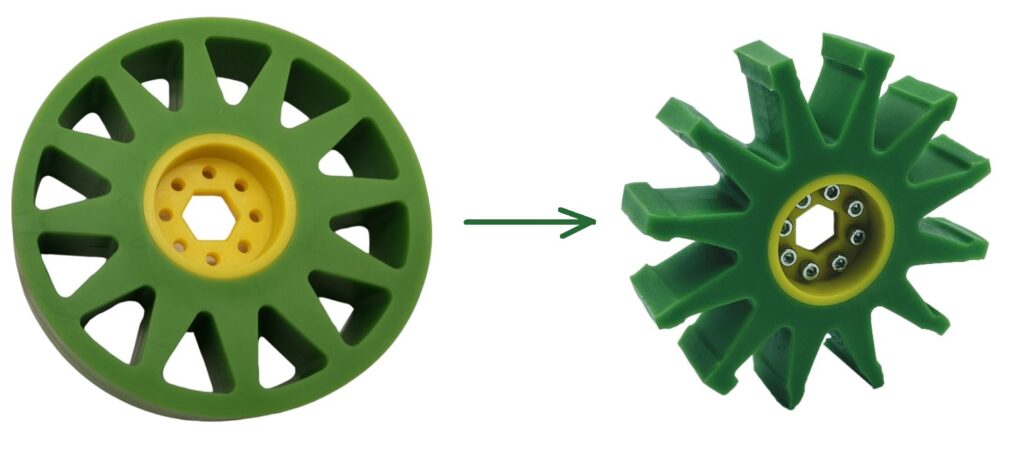
What should you build with? Robot prototypes can be simple. Use what you have on hand – PVC pipe, wood, cardboard, springs, spare parts, and get that roll of duct tape ready. Use clamps, weights, and vices to help hold everything together. Have an old chassis lying around? Use it. You can also 3D print any parts that you don’t have on type for this stage. Studica Robotics also offers a variety of robot parts and robotics components including mechanical structures, motion components, and electronics. Our channel and other structural components as well as motion components are ideal for prototyping. Studica Robotics is utilized in the classroom for teaching, for robot competitions, in the industry, and by hobbyists for prototyping robots and automation cells. Prototyping equipment varies based on the sophistication of the robot being designed.